Lesson
1: Vectors - Fundamentals and Operations
http://www.physicsclassroom.com
Vectors
and Direction
A study of
motion will involve the introduction of a variety of quantities which are used
to describe the physical world. Examples of such quantities include distance,
displacement, speed, velocity, acceleration, force, mass, momentum, energy,
work, power, etc. All these quantities can by divided into two categories - vectors
and scalars. A
vector quantity is a quantity which is fully described by both magnitude and
direction. On the other hand, a scalar quantity is a quantity which is fully
described by its magnitude. The emphasis of this unit is to understand some
fundamentals about vectors and to apply the fundamentals in order to understand
motion and forces which occur in two dimensions.
Examples of
vector quantities which have been previously discussed include displacement, velocity, acceleration, and force. Each of these quantities are
unique in that a full description of the quantity demands that both a magnitude
and a direction are listed. For example, suppose that your teacher tells you
that "a bag of gold is located outside the classroom; to find it, displace
yourself 20 meters." This statement may provide yourself enough
information to pique your interest; yet, not enough information to find the bag
of gold. The displacement required to find the bag of gold has not been fully
described. On the other hand, suppose your teacher tells you that "a bag
of gold is located outside the classroom; to find it, displace yourself from
the center of the classroom door 20 meters in a direction 30 degrees to the
west of north." This statement provides a complete description of the
displacement vector - it lists both magnitude (20 meters) and direction (30
degrees to the west of north) relative to a reference or starting position (the
center of the classroom door). Vector quantities are not fully described unless
both magnitude and direction are listed.

Vector
quantities are often represented by scaled vector diagrams. Vector diagrams depict a vector by
use of an arrow drawn to scale in a specific direction. Vector diagrams were
introduced and used in earlier units to depict the forces acting upon an
object; such diagrams are known as free-body diagrams. An example of a scaled vector
diagram is shown in the diagram at the right to depict a displacement vector. Observe
that there are several characteristics of this diagram which make it an
appropriately drawn vector diagram.
· a scale is clearly listed
·
an
arrow (with arrowhead) is drawn in a specified direction; thus, the vector has
a head and a tail.
·
the magnitude and direction of
the vector is clearly labeled; in this case, the diagram shows the magnitude is
20 m and the direction is (30 degrees West of North).
Vectors can
be directed due East, due West, due South, and due North. But some vectors are
directed northeast (at a 45 degree
angle); and some vectors are even directed northeast,
yet more north than east. Thus, there is a clear need for some form of a
convention for identifying the direction of a vector which is not due
East, due West, due South, or due North. There are a variety of conventions for
describing the direction of any vector. The two conventions which will be
discussed and used in this unit are described below:
1. The direction of a vector is often expressed as an angle of rotation
of the vector about its "tail" from either east, west, north, or south.
For example, a vector can be said to have a direction of 40 degrees North of
West (meaning a vector pointing West has been rotated 40 degrees towards the
northerly direction) of 65 degrees East of South (meaning a vector pointing
South has been rotated 65 degrees towards the easterly direction).
2. The direction of a vector is often expressed as an counterclockwise
angle of rotation of the vector about its "tail" from due East. Using this convention, a
vector with a direction of 30 degrees is a vector which has been rotated 30
degrees in a counterclockwise direction relative to due east. A vector with a
direction of 160 degrees is a vector which has been rotated 160 degrees in a
counterclockwise direction relative to due east. A vector with a direction of
270 degrees is a vector which has been rotated 270 degrees in a counterclockwise
direction relative to due east. This is one of the most common conventions for
the direction of a vector and will be utilized throughout this unit.
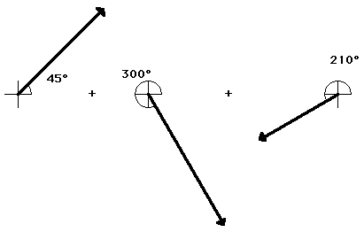
Two
illustrations of the second convention (discussed above) for identifying the
direction of a vector are shown below.

Observe in the first example
that the vector is said to have a direction of 40 degrees. This means that the tail of the vector was pinned down, and
the vector was rotated an angle of 40 degrees in the counterclockwise direction
beginning from due east. Observe in the second example that the vector is said
to have a direction of 240 degrees. This means that the tail of the vector was
pinned down, and the vector was rotated an angle of 240 degrees in the
counterclockwise direction beginning from due east; a rotation of 240 degrees
is equivalent to rotating the vector through two quadrants (180 degrees) and
then an additional 60 degrees into the third
quadrant.
 The magnitude of a vector in a
scaled vector diagram is depicted by the length of the arrow. The arrow is
drawn a precise length in accordance with a chosen scale. For example, the
diagram at the right shows a vector with a magnitude of 20 miles. Since the
scale used for constructing the diagram is 1 cm = 5 miles, the vector
arrow is drawn with a length of 4 cm. That is, 4 cm x (5 miles/1 cm) = 20
miles. Using the same scale (1 cm = 5 miles), a displacement vector
which is 15 miles will be represented by a vector arrow which is 3 cm in
length. Similarly, a 25 mile displacement vector is represented by a 5-cm long
vector arrow. And finally, an 18 mile displacement vector is represented by a
3.6-cm long arrow. See the examples shown below.
The magnitude of a vector in a
scaled vector diagram is depicted by the length of the arrow. The arrow is
drawn a precise length in accordance with a chosen scale. For example, the
diagram at the right shows a vector with a magnitude of 20 miles. Since the
scale used for constructing the diagram is 1 cm = 5 miles, the vector
arrow is drawn with a length of 4 cm. That is, 4 cm x (5 miles/1 cm) = 20
miles. Using the same scale (1 cm = 5 miles), a displacement vector
which is 15 miles will be represented by a vector arrow which is 3 cm in
length. Similarly, a 25 mile displacement vector is represented by a 5-cm long
vector arrow. And finally, an 18 mile displacement vector is represented by a
3.6-cm long arrow. See the examples shown below.

In conclusion, vectors can be
represented by use of a scaled vector diagram. On such a diagram, an arrow is
drawn to represent the vector; the arrow has an obvious tail and arrowhead. The
magnitude of a vector is represented by the length of the arrow; a scale is
indicated (such as, 1 cm = 5 miles) and the arrow is drawn the proper length
according to the chosen scale. The arrow points in the precise direction.
Directions are described by the use of some convention; the most common
convention is that the direction of a vector is the counterclockwise angle of
rotation which that vector makes with due East.
In the
remainder of this lesson, in the entire unit, and even in future units, scaled
vector diagrams and the above convention for the direction of a vector will be
commonly used to describe motion and solve problems concerning motion. For this
reason, it is critical that you have a comfortable understanding of the means
of representing and describing vector quantities. Some practice problems are
available on-line at the following WWW page:
http://www.glenbrook.k12.il.us/gbssci/phys/morehelp/vectdirn/practice.html
Vector
Addition
A variety
of mathematical operations can be performed with and upon vectors. One such
operation is the addition of vectors. Two vectors can be added together to
determine the result (or resultant). This process of adding two or more vectors
has already been discussed in an earlier unit. Recall in our discussion of
Newton's laws of motion, that the net force acting upon an object was
determined by computing the vector sum of all the individual forces acting upon
that object. That is the net force was the result (or resultant) of adding up all the force
vectors. During that unit, the rules for summing vectors (such as force
vectors) was kept relatively simple. Observe the following summations of two
forces:
These rules
for summing vectors were applied to free-body diagrams in order to determine the net force
(i.e., the vector sum of all the individual forces). Sample applications are
shown in the diagram below.

In this unit, the task of summing
vectors will be extended to more complicated cases in which the vectors are
directed in directions other vertical and horizontal directions. For example, a
vector directed up and to the right will be added to a vector directed up and
to the left. For cases such as those shown in the diagrams below, what is the
resultant and how can it be determined?

There are a variety of methods
for determining the magnitude and direction of the result of adding two or more
vectors. The two methods which will be discussed in this lesson and used
throughout the entire unit are:
·
the
Pythagorean theorem and trigonometric methods
·
the head-to-tail method using a scaled vector
diagram
The
Pythagorean theorem is a useful method for determining the result of adding two
(and only two) vectors which make a right angle to each other. The
method is not applicable for adding more than two vectors or for adding vectors
which are not at 90-degrees to each other. The Pythagorean theorem is a
mathematical equation which relates the length of the sides of a right triangle
to the length of the hypotenuse of a right triangle.

To see how the method works,
consider the following problem:
A hiker leaves camp and hikes 11 km, north and then hikes 11 km east. Determine
the resulting displacement of the hiker.

This problem asks to determine
the result of adding two displacement vectors which are at right angles to each
other. The result (or resultant) of walking 11 km north and 11 km east is a
vector directed northeast as shown in the diagram to the right. Since the
northward displacement and the eastward displacement are at right angles to
each other, the Pythagorean theorem can be used to determine the resultant
(i.e., the hypotenuse of the right triangle).
The
resultant of 11 km, north plus 11 km, east is a vector with a magnitude of 15.6
km. Later, the method of determining the
direction of the vector will be discussed. For now, let's test your
understanding with the following two practice problems. In each case, use the
Pythagorean theorem to determine the magnitude of the resultant.
The
direction of vector R in the diagram above can be determined by use of
trigonometric functions. Most students recall the meaning of the useful
mnemonic - SOH CAH TOA - from their course on trigonometry. SOH CAH TOA is a
mnemonic which helps students remember the meaning of the three common
trigonometric functions - sine, cosine, and tangent functions. These three
functions relate the angle of a right triangle to the ratio of the lengths of
two of the sides of a right triangle. The sine function relates the sine of an
angle to the ratio of the length of the side opposite the angle to the length
of the hypotenuse. The cosine function relates the cosine of an angle to the
ratio of the length of the side adjacent the angle to the length of the
hypotenuse. The tangent function relates the tangent of an angle to the ratio
of the length of the side opposite the angle to the length of the side adjacent
to the angle. The three equations below summarize these three functions in
equation form.

These three trigonometric
functions can be applied to the hiker problem in order to determine the direction of the
hiker's displacement. The process begins by the selection of one of the two
angles (other the right angle) of the triangle. Once the angle is selected, any
of the three functions can be used to find the measure of the angle. Write the
function and proceed with the proper algebraic steps to solve for the measure
of the angle. The work is shown below.

Once the measure of the angle
is determined, the direction of the vector can be found. In this case the
vector makes an angle of 45 degrees with due East. Thus, the direction of this
vector is written as 45 degrees. (Recall from earlier in this lesson, that the direction of a vector is the counterclockwise angle of
rotation which the vector makes with due East.)
The measure
of an angle as determined through use of SOH CAH TOA is not always the
direction of the vector. For example, study the following situation in which
the angle of the triangle is determined to be 26.6 degrees using SOH CAH TOA;
yet the direction of the vector is 206.6 degrees.
Test your
understanding of the use of SOH CAH TOA to determine the vector direction by
trying the following two practice problems. In each case, use SOH CAH TOA to
determine the direction of the resultant.


In the above problems, the
magnitude and direction of the sum of two vectors is determined using the
Pythagorean theorem and trigonometric methods (SOH CAH TOA). The procedure is
restricted to the addition of two vectors which make right angles to each
other. When the two vectors which are to be added do not make right angles
to one another, or when there are more than two vectors to add together, we
will employ a method known as the head-to-tail vector addition method. This
method is described below.
The
magnitude and direction of the sum of two or more vectors can also be
determined by use of an accurately drawn scaled vector diagram. Using a scaled
diagram, the head-to-tail method is employed to determine the resultant. This
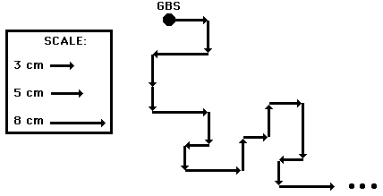
method was first put to use in the Where
Am I? Lab. In that Lab, you were given a set of 18 directions to follow. Starting
at Glenbrook South High School, these 18 displacement vectors were added together in consecutive fashion to
determine the result of adding the set of 18 directions. During the process,
you measured out 5 cm, East from the school; where this measurement ended, the
next measurement began. You repeated the process for all 18 directions. Each
time, where one measurement ended, the next measurement began. In essence, you
were using the head-to-tail method of vector addition.
The head-to-tail method
involves drawing a vector to scale on a sheet of paper beginning at a
designated starting position; where the head of this vector ends the tail of
the next vector begins (thus, head-to-tail
method). The process is repeated for all vectors which are added. Once all
vectors have been added head-to-tail, the resultant is drawn from the tail of
the first vector to the head of the last vector; i.e., from start to finish. Once
the resultant is drawn, its length can be measured and converted to real units using the given scale. The direction of
the resultant can be determined by using a protractor and measuring its
counterclockwise angle of rotation from due East.
The
following step-by-step method for applying the head-to-tail method to determine
the sum of two or more vectors is given below.
1.
Choose
a scale and indicate it on a sheet of paper (the best choice of scale is one
which will result in a diagram which is as large as possible, yet fits on the
sheet of paper).
2.
Pick
a starting location and draw the first vector to scale in the indicated direction. Label the magnitude and
direction of the scale on the diagram (e.g., SCALE: 1 cm = 20 m).
3.
Starting
from where the head of the first vector ends, draw the first vector to scale in the indicated direction. Label
the magnitude and direction of the vector on the diagram.
4.
Repeat
steps 2 and 3 for all vectors which are to be added
5. Draw the resultant from the tail of the first vector to the head of the last vector. Label this vector as "Resultant" or simply "R."
6.
Using
a ruler, measure the length of the resultant and determine its magnitude by
converting to real units using the scale (4.4 cm x 20 m/1 cm = 88 m).
7.
Measure
the direction of the resultant using the counterclockwise convention discussed earlier in this lesson.
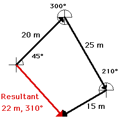
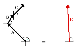
An example
of the use of the head-to-tail method is illustrated below. The problem
involves the addition of three vectors:
The head-to-tail method is
employed as described above and the resultant is determined (drawn in red). Its
magnitude and direction is labeled on the diagram.
SCALE: 1 cm = 5 m
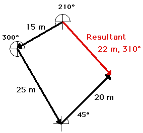
Interestingly enough, the
order in which three vectors are added is insignificant; the resultant will
still have the same magnitude and direction. For example, consider the addition
of the same three vectors in a different order.
15 m, 210 deg. + 25 m, 300 deg. + 20 m, 45 deg.
SCALE: 1 cm = 5 m

When added together in this
different order, these same three vectors still produce a resultant with the
same magnitude and direction as before (22 m, 310 deg.). The order in which
vectors are added using the head-to-tail method is insignificant.
SCALE: 1 cm = 5 m
Resultants
The resultant
is the vector sum of two or more vectors. It is the result of adding vectors together. If displacement vectors A,
B, and C are added together, the result will be vector R. As shown in the
diagram, vector R can be determined by the use of an accurately drawn, scaled, vector addition diagram.
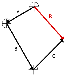
To say that vector R is the resultant displacement of displacement
vectors A, B, and C is to say that a person who walked with displacements A,
then B, and then C would be displaced by the same amount as a person who walked
with displacement R. Displacement vector R gives the same result as displacement vectors A + B + C. That is why it can be
said that
A + B + C = R
The above
discussion pertains to the result of adding displacement vectors; when
displacement vectors are added, the result is a resultant displacement. But any two vectors can be added as long as
they are the same vector quantity. Add two or more velocity vectors and the
result is a resultant velocity; add
two or more force vectors and the result is a resultant force; add two or more momentum vectors and the result is
...
In all such
cases, the resultant vector (whether a displacement vector, force vector,
velocity vector, etc.) is the result of adding the individual vectors. It is
the same thing as adding A + B + C + ... . "To do A + B + C is the same as
to do R."
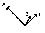 As an example, consider a football
player who gets hit simultaneously by three players on the opposing team
(players A. B. and C). The football player experiences three different applied
forces. Each applied force contributes to a total or resulting force. If the
three forces are added together using methods of vector addition (discussed earlier), then the resultant vector R can be determined. In this case, to
experience the three forces A, B and C is the same as experiencing force R. To
be hit by players A, B, and C would result in the same force as being hit by
one player applying force R. "To do A + B + C is the same as to do
R." Vector R is the same result as vector A + B + C!!
As an example, consider a football
player who gets hit simultaneously by three players on the opposing team
(players A. B. and C). The football player experiences three different applied
forces. Each applied force contributes to a total or resulting force. If the
three forces are added together using methods of vector addition (discussed earlier), then the resultant vector R can be determined. In this case, to
experience the three forces A, B and C is the same as experiencing force R. To
be hit by players A, B, and C would result in the same force as being hit by
one player applying force R. "To do A + B + C is the same as to do
R." Vector R is the same result as vector A + B + C!!
In summary, the resultant is
the vector sum of all the individual vectors. The resultant is the result of
combining the individual vectors together. The resultant can be determined by
adding the individual forces together using vector addition methods.
Vector
Components
A vector is a quantity which has magnitude
and direction. Displacement, velocity, acceleration, and force are the vector quantities which we
have discussed thus far in our course. In the first couple of units of our
course, all vectors which we discussed were simply directed up, down, left or right.
When there was a free-body diagram depicting the forces acting upon an object,
those forces were directed in one
dimension - up, down, left or right. When an object had an acceleration and
we described its direction, it was directed in one dimension - up, down, left or right. Now in this unit, we begin
to see examples of vectors which are directed in two dimensions - upward and rightward, northward and westward,
eastward and southward, etc.
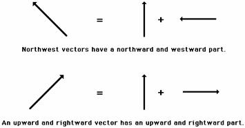
In situations in which vectors
are directed at angles to the customary coordinate axes, a useful mathematical
trick will be employed to transform
the vector into two parts, with each part being directed along the coordinate
axes. For example, a vector which is directed northwest can be thought of as
having two parts - a northward and a westward part. A vector which is directed
upward and rightward can be thought of as having two parts - an upward and a
rightward part.
Any vector
directed in two dimensions can be thought of as having an influence in two
different directions. That is, it can be thought of as having two parts. Each
part of a two-dimensional vector is known as a component. The components of a
vector depict the influence of that vector in a given direction. The combined
influence of the two components is equivalent to the influence of the single two-dimensional
vector. The single two-dimensional vector could be replaced by the two
components.
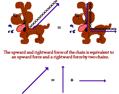
If Fido's
dog chain is stretched upward and rightward and pulled tight by his master,
then the tensional force in the chain has two components - an upward and a
rightward component. To Fido, the influence of the chain on his body is
equivalent to the influence of two chains on his body - one pulling upward and
the other pulling rightward. If the single chain were replaced by two chains
(each one having the magnitude and direction of the components), the Fido would
not know the difference. This is not because Fido is dumb (a quick glance at his picture reveals that he is certainly
not that), but rather because the combined influence of the two components is
equivalent to the influence of the single two-dimensional vector.
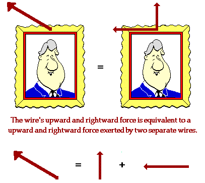
 Consider a picture which is hung to
a wall by means of two wires which are stretched vertically and horizontally. Each
wire exerts a tensional force upon the picture to support its weight. Since
each wire is stretched in two dimensions (both vertically and horizontally),
the tensional force of each wire has two components - a vertical and a
horizontal component. Focusing on the wire on the left, we could say that the
wire has a leftward and an upward component. This is to say that the wire on
the left could be replaced by two wires, one pulling leftward and the other
pulling upward. If the single wire were replaced by two wires (each one having
the magnitude and direction of the components), then there would be no effect
upon the stability of the picture. The combined influence of the two components
is equivalent to the influence of the single two-dimensional vector.
Consider a picture which is hung to
a wall by means of two wires which are stretched vertically and horizontally. Each
wire exerts a tensional force upon the picture to support its weight. Since
each wire is stretched in two dimensions (both vertically and horizontally),
the tensional force of each wire has two components - a vertical and a
horizontal component. Focusing on the wire on the left, we could say that the
wire has a leftward and an upward component. This is to say that the wire on
the left could be replaced by two wires, one pulling leftward and the other
pulling upward. If the single wire were replaced by two wires (each one having
the magnitude and direction of the components), then there would be no effect
upon the stability of the picture. The combined influence of the two components
is equivalent to the influence of the single two-dimensional vector.
Consider an airplane which is
flying from O'Hare International Airport to a destination in Canada. Suppose
that the plane is flying in such a manner that its resulting displacement
vector is northwest. If this is the case, then the displacement of the plane
has two components - a component in the northward direction and a component in
the westward direction. This is to say that the plane would have the same
displacement if it were to take the trip into Canada in two segments - one
directed due North and the other directed due West. If the single displacement
vector were replaced by these two individual displacement vectors, then the
passengers in the plane would end up in the same final position. The combined
influence of the two components is equivalent to the influence of the single
two-dimensional displacement.

Any vector directed in two
dimensions can be thought of as having two different components. The component
of a single vector describes the influence of that vector in a given direction.
In the next part of this lesson, we will investigate two methods
for determining the magnitude of the components. That is, we will investigate how much influence a vector exerts in a
given direction.
Vector
Resolution
As
mentioned earlier in this lesson, any vector directed at an angle to
the horizontal (or the vertical) can be thought of as having two parts (or
components). That is, any vector directed in two dimensions can be thought of
as having two components. For example, if a chain pulls upward at an angle on
the collar of a dog, then there is a tensional force directed in two
dimensions. This tensional force has two components: an upward and a rightward
component. As another example, consider an airplane which is displaced
northwest from O'Hare International Airport (in Chicago) to a destination in
Canada. The displacement vector of the plane is in two dimensions (northwest). Thus,
this displacement vector has two components: a northward and a westward
component.
In this
unit, we learn two basic methods for determining the magnitudes of the
components of a vector directed in two dimensions. The process of determining
the magnitude of a vector is known as vector
resolution. The two methods of vector resolution which we will examine are
· the parallelogram method
The
parallelogram method of vector resolution involves using an accurately drawn,
scaled vector diagram to determine the components of the vector. Briefly put,
the method involves drawing the vector to scale in the indicated direction,
sketching a parallelogram around the vector such that the vector is the
diagonal of the parallelogram, and determining the magnitude of the components
(the sides of the parallelogram) using the scale. A step-by-step procedure for
using the parallelogram method of vector resolution is:
1.
select
a scale and accurately draw the vector to scale in the indicated direction.
2.
sketch
a parallelogram around the vector: beginning at the tail of the vector, sketch vertical and
horizontal lines; then sketch horizontal and vertical lines at the head of the vector; the sketched lines
will meet to form a parallelogram.
3.
draw
the components of the vector; the components are the sides of the parallelogram; be sure to place arrowheads on these
components to indicate their direction (up, down, left, right).
4.
meaningfully
label the components of the vectors with symbols to indicate which component is
being represented by which side; a northward force component would be labeled Fnorth;
a rightward velocity component might be labeled vx; etc.
5.
measure
the length of the sides of the parallelogram and use the scale to determine the magnitude of the components in real units; label the magnitude on the diagram.
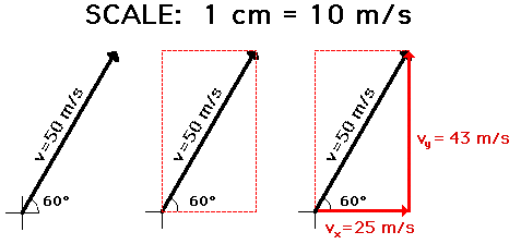
The
step-by-step procedure above is illustrated in the diagram below to show how a
velocity vector with a magnitude of 50 m/s and a direction of 60 degrees above
the horizontal may be resolved into two components. The diagram shows that the
vector is first drawn to scale in the indicated direction; a parallelogram is
sketched about the vector; the components are labeled on the diagram; and the
result of measuring the length of the vector components and converting to m/s
using the scale. (NOTE: because different computer monitors have different
resolutions, the actual length of the vector on your monitor may not be 5 cm.)
The trigonometric method of
vector resolution involves using trigonometric functions to determine the
components of the vector. Earlier in lesson 1, the use of trigonometric functions
to determine the direction of a vector was described. Now, in this part of
lesson 1, trigonometric functions will be used to determine the components of a
single vector. Recall from the earlier discussion that trigonometric functions relate
the length of the sides of a right triangle to the angle of a right triangle. As
such, trigonometric functions can be used to determine the length of the sides
of a right triangle if one angle and the length of one side are known.
The method
of employing trigonometric functions to determine the components of a vector
are as follows:
1.
construct
a sketch (no scale needed) of the vector in the indicated direction; label its
magnitude and the angle which it makes with the horizontal.
2.
draw
a rectangle about the vector such that the vector is the diagonal of the
rectangle; beginning at the tail of the vector, sketch vertical and horizontal
lines; then sketch horizontal and vertical lines at the head of the vector; the sketched lines
will meet to form a parallelogram.
3.
draw
the components of the vector; the components are the sides of the rectangle; be sure to place arrowheads on these
components to indicate their direction (up, down, left, right).
4.
meaningfully
label the components of the vectors with symbols to indicate which component is
being represented by which side; a northward force component would be labeled
F-north; a rightward force velocity component might be labeled v-x; etc.
5.
to
determine the length of the side opposite the indicated angle, use the sine
function; substitute the magnitude of the vector for the length of the
hypotenuse; use some algebra to solve the equation for the length of the side
opposite the indicated angle.
6.
repeat
the above step using the cosine function to determine the length of the side
adjacent to the indicated angle.
The above method is
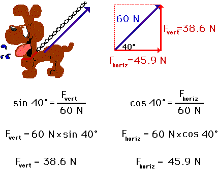
illustrated below for determining the components of the force acting upon Fido.
As the 60-Newton tensional force acts upward and rightward on Fido at an angle
of 40 degrees, the components of this force can be determined using
trigonometric functions.
In
conclusion, a vector directed in two dimensions has two components - that is,
an influence in two separate directions. The amount of influence in a given
direction can be determined using methods of vector resolution. Two methods of
vector resolution have described here - a graphical method and a trigonometric method.
Relative
Velocity and Riverboat Problems
On
occasion objects move within a medium which is moving with respect to an
observer. For example, an airplane usually encounters a wind - air which is
moving with respect to an observer on the ground below. As another example, a
motor boat in a river is moving amidst a river current - water which is moving
with respect to an observer on dry land. In such instances as this, the
magnitude of the velocity of the moving object (whether it be a plane or a
motor boat) with respect to the observer on land will not be the same as the
speedometer reading of the vehicle. That is to say, the speedometer on the
motor boat might read 20 mi/hr; yet the motor boat might be moving relative to
the observer on shore at a speed of 25 mi/hr. Motion is relative to the
observer. The observer on land, often named (or misnamed) the "stationary
observer" would measure the speed to be different than that of the person
on the boat. The observed speed of the boat must always be described relative
to who the observer is.
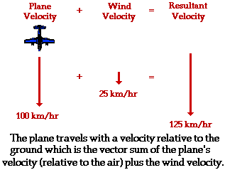
To
illustrate this principle, consider a plane flying amidst a tailwind. A tailwind is merely a wind which approaches the
plane from behind, thus increasing its resulting velocity. If the plane is
traveling at a velocity of 100 km/hr with respect to the air, and if the wind
velocity is 25 km/hr, then what is the velocity of the plane relative to an
observer on the ground below? The resultant velocity of the plane (that is, the
result of the wind velocity contributing to the velocity due to the plane's
motor) is the vector sum of the velocity of the plane and the velocity of the
wind. This resultant velocity is quite easily determined if the wind approaches
the plane directly from behind. As shown in the diagram below, the plane
travels with a resulting velocity of 125 km/hr relative to the ground.
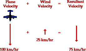
If the plane
encounters a headwind, the resulting velocity will be less than 100 km/hr. Since
a headwind is a wind which approaches the plane from the front, such a wind
would decrease the plane's resulting velocity. Suppose a plane traveling with a
velocity of 100 km/hr with respect to the air meets a headwind with a velocity
of 25 km/hr. In this case, the resultant velocity would be 75 km/hr; this is
the velocity of the plane relative to an observer on the ground. This is
depicted in the diagram below.
Now consider a
plane traveling with a velocity of 100 km/hr, South which encounters a side wind of 25 km/hr, West. Now what would the resulting
velocity of the plane be? This question can be answered in the same manner as
the previous questions. The resulting velocity of the plane is the vector sum
of the two individual velocities. To determine the resultant velocity, the
plane velocity (relative to the air) must be added to the wind velocity. This
is the same procedure which was used above for the headwind and the tailwind
situations; only now, the resultant is not as easily computed. Since the two
vectors to be added - the southward plane velocity and the westward wind
velocity - are at right angles to each other, the Pythagorean theorem can be used. This is illustrated in the diagram below.
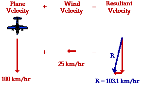
In this situation
of a side wind, the southward vector can be added to the westward vector using
the usual methods of vector addition. The magnitude of the
resultant velocity is determined using Pythagorean theorem. The algebraic steps
are as follows:
(100 km/hr)2 + (25
km/hr)2 = R2
10 000 km2/hr2
+ 625 km2/hr2 = R2
10 625 km2/hr2
= R2
SQRT(10 625 km2/hr2)
= R
103.1 km/hr = R
The direction of the resulting
velocity can be determined using a trigonometric function. Since the plane
velocity and the wind velocity form a right triangle when added together in
head-to-tail fashion, the angle between the resultant and the southward vector
can be determined using either the sine, cosine, or tangent functions.
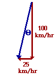 The tangent
function
can be used; this is shown below:
tan (theta) = (opposite/adjacent)
tan (theta) = (25/100)
theta - invtan (25/100)
theta =
14.0 degrees
If the resultant velocity of the
plane makes a 14.0 degree angle with the southward direction (theta in the
above diagram),then the direction of the resultant is 256 degrees. Like any
vector, the resultant's direction is measured as a
counterclockwise angle of rotation from due East.
The
effect of the wind upon the plane is similar to the effect of the river current
upon the motor boat. If a motor boat were to head straight across a river (that
is, if the boat were to point its bow straight towards the other side), it
would not reach the shore directly across from its starting point. The river
current influences the motion of the boat and carries it downstream. The motor
boat may be moving with a velocity of 4 m/s directly across the river, yet the
resultant velocity of the boat will be greater than 4 m/s and at an angle in
the downstream direction. While the speedometer of the boat may read 4 m/s, its
speed with respect to an observer on the shore will be greater than 4 m/s.

The
resultant velocity of the motor boat can be determined in the same manner as
was done for the plane. The resultant velocity of the boat is the vector sum of
the boat velocity and the river velocity. Since the boat heads straight across
the river and since the current is always directed straight downstream, the two
vectors are at right angles to each other. Thus, the Pythagorean theorem can be used to determine the resultant velocity. Suppose
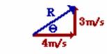
that the river was moving with a velocity of 3 m/s, North and the motor boat
was moving with a velocity of 4 m/s, East. What would be the resultant velocity
of the motor boat (i.e., the velocity relative to an observer on the shore)? The
magnitude of the resultant can be found as follows:
(4.0 m/s)2 + (3.0 m/s)2
= R2
16 m2/s2 + 9
m2/s2 = R2
25 m2/s2 = R2
SQRT (25 m2/s2)
= R
5.0 m/s =
R
 The direction of the resultant is the
counterclockwise angle of rotation which the resultant vector makes with due
East. This angle can be determined using a trigonometric function as shown
below.
The direction of the resultant is the
counterclockwise angle of rotation which the resultant vector makes with due
East. This angle can be determined using a trigonometric function as shown
below.
tan (theta) = (opposite/adjacent)
tan (theta) = (3/4)
theta - invtan (3/4)
theta =
36.9 degrees
Consider
the following example.
|
Example 1 A motor
boat traveling 4 m/s, East encounters a current traveling 3.0 m/s, North. g. What is the resultant velocity of
the motor boat? h. If the width of the
river is 80 meters wide, then how much time does it take the boat to travel
shore to shore? i.
What distance downstream does the boat reach the
opposite shore? |
The
solution to the first question has already been shown in the above discussion. The resultant velocity
of the boat is 5 m/s at 36.9 degrees. We will start in on the second question.
The
river is 80-meters wide; that is, the distance from shore to shore as measured
straight across the river is 80 meters. The time to cross this 80-meter wide
river can be determined by rearranging and substituting into the average speed
equation.
time =
distance/(ave. speed)
The
distance is 80 m can be substituted into the numerator. But what about the
denominator? What value should be used for average speed? Should 3 m/s (the
current velocity), 4 m/s (the boat velocity), or 5 m/s (the resultant velocity)
be used as the average speed value for covering the 80 meters? With what
average speed is the boat traversing the 80 meter wide river? Most students
want to use the resultant velocity in the equation since that is the actual
velocity of the boat with respect to the shore. Yet the value of 5 m/s is the
speed at which the boat covers the diagonal dimension of the river. And the
diagonal distance across the river is not known in this case. If one knew the distance C in the diagram below, then the average speed C could be used to calculate the
time to reach the opposite shore. Similarly, if one knew the distance B in the diagram below, then the average speed B could be used to calculate the
time to reach the opposite shore. And finally, if one knew the distance A in the diagram below, then the average speed A could be used to calculate the
time to reach the opposite shore.
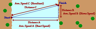
In our problem,
the 80 m corresponds to the distance A, and so the average speed of 4 m/s
(average speed in the direction straight across the river) should be
substituted into the equation to determine the time.
time =
(80 m)/(4 m/s) = 20 s
It
requires 20 s for the boat to travel across the river. During this 20 s of
crossing the river, the boat also drifts downstream. Part c of the problem asks "What
distance downstream does the boat reach the opposite shore?" The same
equation must be used to calculate this downstream
distance. And once more, the question arises, which one of the three
average speed values must be used in the equation to calculate the distance
downstream? The distance downstream corresponds to Distance
B on
the above diagram. The speed at which the boat covers this distance corresponds
to Average Speed B on the diagram above
(i.e., the speed at which the current moves - 3 m/s). And so the average speed
of 3 m/s (average speed in the downstream direction) should be substituted into
the equation to determine the time.
distance
= ave. speed * time = (3 m/s) * (20 s)
distance
= 60 m
The boat is carried 60 meters downstream during
the 20 seconds it takes to cross the river.
The
mathematics of the above problem is no more difficult than dividing or
multiplying two numerical quantities by each other. The mathematics is easy!
The difficulty of the problem is conceptual in nature; the difficulty lies in
deciding which numbers to use in the equations. That decision emerges from
one's conceptual understanding (or unfortunately, one's misunderstanding) of
the complex motion which is occurring. The motion of the river boat can be
divided into two simultaneous parts - a motion in the direction straight across
the river and and a motion in the downstream direction. These two parts (or
components) of the motion occur simultaneously for the same time duration
(which was 20 seconds in the above problem). The decision as to which velocity
value or distance value to use in the equation must be consistent with the diagram above. The
boat's motor is what carries the boat across the river the Distance A; and so any calculation involving the Distance A must involve the speed value labeled as Speed A (the boat speed relative to the water). Similarly, it is
the current of the river which carries the boat downstream for the Distance B; and so any calculation involving the Distance B must involve the speed value labeled as Speed B (the river speed). Together, these two parts (or components)
add up to give the resulting motion of the boat. That is, the across-the-river
component of displacement adds to the downstream displacement to equal the
resulting displacement. And likewise, the boat velocity (across the river) adds
to the river velocity (down the river) to equal the resulting velocity. And so
any calculation of the Distance C or the Average Speed C ("Resultant
Velocity") can be performed using the Pythagorean theorem.
Now
to illustrate an
important point, let's try a second example problem which is similar to the first example
problem. Make an
attempt to answer the three questions and then use the pop-up menu to check your answer.
|
Example 2 A motor
boat traveling 4 m/s, East encounters a current traveling 7.0 m/s, North. j.
What is the resultant velocity of the motor boat? k.
If the width of the river is 80 meters wide, then
how much time does it take the boat to travel shore to shore? l.
What distance downstream does the boat reach the
opposite shore? |
An
important concept
emerges from the analysis of the two example problems above. In Example 1, the
time to cross the 80-meter wide river (when moving 4 m/s) was 20 seconds. This
was in the presence of a 3 m/s current velocity. In Example 2, the current velocity
was much greater - 7 m/s - yet the time to cross the river remains unchanged. In
fact, the current velocity itself has no effect upon the time required for a
boat to cross the river. The river moves downstream parallel to the banks of
the river; as such, there is no way that the current is capable of assisting a
boat in crossing a river. While the increased current may effect the resultant
velocity - making the boat travel with a greater speed with respect to an
observer on the ground - it does not increase the speed in the direction across
the river. The increased resultant velocity is only a direction pointing down
the river. It is often said that "perpendicular components of motion are
independent of each other." As applied to river boat problems, this would
mean that an across-the-river variable would be independent of (i.e., not be
effected by) a downstream variable. The time to cross the river is dependent
upon the velocity at which the boat crosses the river. It is only the component
of motion directed across the river (i.e., the boat velocity) which effects the
time to travel the distance directly across the river (80 m in this case). The
component of motion perpendicular to this direction - the current velocity -
only effects the distance which the boat travels downstream. This concept of
perpendicular components of motion will be investigated in more detail in the next
part of Lesson 1.
Check Your Understanding
1.
A plane can travel with a speed of 80 mi/hr with respect to the air. Determine
the resultant velocity of the plane (magnitude only) if it encounters a
m. 10 mi/hr headwind.
n. 10 mi/hr tailwind.
o. 10 mi/hr crosswind.
p. 60 mi/hr crosswind.
2.
A motor boat traveling
5 m/s, East encounters a current traveling 2.5 m/s, North.
q. What is the resultant velocity of
the motor boat?
r.
If the width of the river is 80 meters wide, then how much time does it
take the boat to travel shore to shore?
s.
What distance downstream does the boat reach the opposite shore?
3.
A motor boat traveling
5 m/s, East encounters a current traveling 2.5 m/s, South.
t.
What
is the resultant velocity of the motor boat?
u. If the width of the
river is 80 meters wide, then how much time does it take the boat to travel
shore to shore?
What
distance downstream does the boat reach the opposite shore?
4.
A motor boat traveling
6 m/s, East encounters a current traveling 3.8 m/s, South.
v. What is the resultant velocity of
the motor boat?
w. If the width of the
river is 120 meters wide, then how much time does it take the boat to travel
shore to shore?
x.
What distance downstream does the boat reach the opposite shore?
5.
If the current velocity in question #4 were increased to 5 m/s, then
y. how much time would be
required to cross the same 120-m wide river?
z.
what distance downstream would the boat travel during this time?