Light is a form of energy
visible to the human eye that is radiated by moving charged particles. There are
many unanswered questions about light. Light is very hard to study due to its
high speed. One major question about light is the uncertainty of whether light
is a wave or whether it is a particle. There is some evidence pointing in both
directions but no conclusive proof confirms that it can be classified as either
one. Scientists have learned through experimentation that light behaves like a
particle at times, and like a wave at other times. Whenever light acts like a
particle, we called the particles that make up the light either a photon or quantum. In 1900, Max Planck
proposed the existence of a light quantum, a finite packet of energy which is a
photon.
Photons may be described as tiny packets of light
energy. Photons are unlike conventional particles, such as specks of dust,
because photons do not have to have a specific volume in space. Photons are
always arranged in an electromagnetic wave of a definite frequency which
indicates that photons are part of a wave. The frequency of the photon forms a single
spectrum line that represents a particular wavelength or colour. In 1900, a
German physicist named Max Planck discovered that light energy is carried by
photons. He found that the energy of a photon is equal to the frequency of its
electromagnetic wave multiplied by a constant called “h”, which stands for
Planck’s constant. However, this constant is very small because each photon
carries little energy. Using the Joule as the unit of energy, Planck's constant
is 6.626 x 10^(-20) joules per second in scientific
notation. Photons are different from particles of matter in that they have no
mass and always move at the constant speed of light which is 300,000 km/sec
(186,000 mi/sec). Sir Isaac Newton
was for the idea that light is a particle (photon),
although,
Another way light is thought of as travelling is in
the form of a wave. It is thought this because light also shows wavelike
characteristics. When light diffracts, or bends slightly as it passes around a
corner, it shows wavelike behavior. If it were a
particle, it would not bend around a corner. The waves are called “matter
waves”. Matter waves have a specific wavelength and the wavelength is inversely
proportional to the particle’s momentum. Matter waves also explain the
arrangement of electrons in separate orbits. The waves associated with light
are called electromagnetic waves because they consist of changing electric and
magnetic fields. A wave is a continuous phenomenon, which means that when it
travels, its electromagnetic field must move at each of the infinite number of
points in every small part of space. When we add heat to any system to raise
its temperature, the energy is shared equally among all the parts of the system
that can move. When this idea is applied to light as a wave, with an infinite
number of moving parts, it would require an infinite amount of heat to give all
the parts equal energy. But thermal radiation, the process in which heated
objects emit electromagnetic waves, occurs in nature without having to add an
infinite amount of heat. The wave theory of atomic particles has given
scientists a greater understanding of the structure of atoms and their nuclei.
A debate arises: “Is light a wave or a particle?” It
can’t be both because the models of waves and particles are very different. The
way they behave when travelling and when passing through mediums is very
different. It seems that your conclusion depends on what type of experiment
you are doing. In 1905, Einstein said that a ray of light travels in the
path of the photon. The traveling photons are in
great number and travel in straight lines. To understand the nature of light,
and how it is normally created, it is necessary to study matter at its atomic
level. The motion of electrons, leads to the emission of light in most sources.
The first successful theory of light wave motion in
three dimensions was proposed by the Dutch scientist Christiaan Huygens in 1678. Huygens suggested that light wave peaks form
surfaces like the layers of an onion. In a vacuum, or a uniform material, the
surfaces are spherical. These wave surfaces advance, or spread out, through
space at the speed of light. Huygens also suggested that each point on a wave
surface can act like a new source of smaller spherical waves, which may be
called wavelets, that are in step with the wave at
that point. The envelope of all the wavelets is a wave surface. An envelope is
a curve or surface that touches a whole family of other curves or surfaces like
the wavelets. This construction explains how light seems to spread away from a
pinhole rather than going in one straight line through the hole. The same
effect blurs the edges of shadows. Huygens's principle, with minor
modifications, accurately describes all forms of wave motion.
There is also a theory which light is said to travel
in both a wavelike manner and a particle-like manner. This is called the wave-particle duality and was proposed
in 1924 by de Broglie, who also developed the idea of
the “matter wave” which is a basic part of the wave-particle duality theory.
The wave-particle duality theory says that photons do have a mass and travel
along on a wave. This was a combination of the wave and particle theories of
light and now is the generally accepted explanation of the way light travels.
Heisenberg showed that the wave-particle duality leads to the uncertainty
principle. The uncertainty principle states that the position and velocity of a
particle cannot simultaneously be measured with exactness. This principle is
valid because a particle has certain wave properties. The wave-particle duality
theory made since after Einstein connected matter and energy.
Einstein taught us that matter is just another form of
very, very condensed energy. Albert Einstein's theory into the equivalence of
matter and energy, expressed as the famous equation: E=mc2, has been
confirmed countless times. At the time, it was much easier to demonstrate light
as a wave. The process also occurs naturally when a star shines because the
atoms in its core fuse, transforming a very small sliver of matter into light.
And when particles of matter and antimatter meet, they annihilate each other in
a burst of energy. But like any equation, E=mc2 works both ways. Meaning that it should be possible to convert massive amounts of
energy into small amounts of matter. A team of physicists has now
transformed light into matter. “We're able to turn optical photons into matter,”
says
http://www.studyphysics.ca/20/unit4/wavemodel/particlevwave/note.htm
During the later part of his
life
- Light travels in straight lines. When you
throw something like a baseball, it doesn’t suddenly make a right turn
and start going in another direction. Particles always move in straight
lines, and light seems to move in straight lines.
- Light can travel through a vacuum. Waves need
a substance, a medium, to move through. Sound travels through air, waves
travel through water, etc. By
On the other side of the
argument you had people like Christian Huygens, who although he was basically
unknown, had a lot of carefully thought out physics to back up his claims that
light was a wave.
Huygens had a tough job, since not only does he have to disprove
- Huygens
focused most of his attack on the first point outlined above. He had to be
able to show that light would diffract when it passed through openings or
around obstacles.
- He looked at
the work of Francesco Grimaldi, who had shown
the edges of shadows are not perfectly sharp. If light was a particle
they should be. If light is a wave, we can explain that fuzziness as the
diffraction of the waves partly around the object.
Huygens developed this idea further in order to explain the diffraction
of waves around obstacles or through openings.
- He said we
should imagine the crest of a wave as being made up of an infinite number
of tiny waves, which he called wavelets.
- As these
wavelets pass through an opening or an obstacle they will begin to spread out
again… this is what leads to diffraction.
- Latter, when
Thomas Young showed that light does diffract and interfere when it passes
through openings (which we will study shortly),
Huygens had the proof he needed. Light was a wave.
There was still resistance to Huygen’s
theories, mostly because
- Huygens came
up with a separate argument that would seem to indicate that the particle
model is simply wrong.
- When light
hits the boundary between two media (like air and water) part of the light
is transmitted
(and refracts), while part of it is reflected.
- Using a wave
model of light Huygens was able to show that waves could do this. If you
measure the amount of light reflected and the amount that was refracted,
it adds up to the original wave.
- When
- He said that
when light particles reach the surface, they have “fits” (just like when
you had a fit when you were 3 years old and you didn’t get what you
wanted). Some of the particles “decide” to go into the water, while the
rest “decide” to bounce off.
- Given that
this is such a pathetic response,
- In the end the
wave model of light became the accepted model!
http://www.smartpedia.com/smart/browse/Light_wave
http://www.qmw.ac.uk/~zgap118/2/yds.html
http://galileo.phys.virginia.edu/classes/252/photoelectric_effect.html
Early
Greek ideas
In 55 BC Lucretius, continuing the ideas of earlier atomists, wrote that light
and heat from the Sun were composed of minute particles.
10th
century optical theory
The scientist Abu Ali al-Hasan ibn al-Haytham
(965-c.1040), also known as Alhazen, developed a broad theory that explained vision,
using geometry and anatomy, which stated that each point on an illuminated area
or object radiates light rays in every direction, but that only one ray from
each point, which strikes the eye perpendicularly, can be seen. The other rays
strike at different angles and are not seen. He used the example of the pinhole
camera, which produces an inverted image, to support his argument. Alhazen held light rays to be streams of minute particles
that travelled at a finite speed. He improved Ptolemy's theory of the
refraction of light. Alhazen's work did not become
known in
Particle theory
Pierre
Gassendi, an atomist, proposed a
particle theory of light which was published posthumously in the 1660s. Isaac
Newton studied Gassendi's work at an early age, and
preferred his view to Descartes' theory of the 'plenum'. He stated in his Hypothesis
of Light of 1675 that light was
composed of corpuscles (particles of matter) which were emitted in all
directions from a source. One of
Newton's theory could be used to predict the reflection of light, but
could only explain refraction by incorrectly
assuming that light accelerated upon entering a denser medium because the gravitational pull was greater.
The
'plenum'
Descartes held that light
was a disturbance of the 'plenum', the continuous substance of which the
universe was composed. In 1637 he published a
theory of the refraction of light which wrongly assumed that light travelled
faster in a denser medium, by analogy with the behaviour of sound waves. Descartes'
theory is often regarded as the forerunner of the wave theory of light.
Wave theory
In the 1660s Robert Hooke published a wave theory of light. Christian
Huygens worked out his own wave theory of light in 1678, and published it in
his Treatise on light in 1690. He proposed that
light was emitted in all directions as a series of waves in a medium called the
'aether'. As waves are not affected by gravity, it
was assumed that they slowed down upon entering a denser medium. The wave
theory predicted that light waves could interfere with each other like sound
waves (as noted in the 18th
century by Thomas Young), and that light could be polarized. Young showed by
means of a diffraction experiment that light behaved as waves. He also proposed
that different colours were caused by
different wavelengths of light, and
explained colour vision in terms of three-coloured receptors in the eye.
Another supporter of the wave theory was Euler. He argued in Nova
theoria lucis et colorum (1746) that diffraction could more easily
be explained by a wave theory.
Later, Fresnel independently
worked out his own wave theory of light, and presented it to the Académie des Sciences in 1817. Poisson added to Fresnel's mathematical work to produce a convincing
argument in favour of the wave theory, helping to overturn
The weakness of the wave theory was that light waves,
like sound waves, would need a medium for transmission. A hypothetical substance
called the luminiferous aether was proposed, but
its existence was later disproved.
Foucault's result in
favour of the wave theory
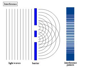
►Young Two-Slit Experiment
One of the most important
experiments of wave theory is that of Young's double slits. It is a clear example
of the diffraction of light conducted with essentially basic scientific
equipment.
Thomas Young was a not only a physicist but also a
physician and and Egyptologist, who was responsible
for deciphering the Rosetta stone. He devised an experiment in the early 1800's
that proved that light is a wave. The experiment has been used subsequently to
show that wave behaviour exists in many other areas of nature and therefore it
is worth spending a little time going into the experiment in detail.
When two light beams interact they create interference
which can be constructive or destructive as we have discussed earlier. The
places where constructive and destructive interference occur are subject to
constant change, since em waves emitted are capable
of varying phase. Using one light source and splitting it into two beams you
can create two coherent sources, meaning they are of identical frequencies and
have a constant phase difference (the distance between a peak of wave 1 and
wave 2 is always the same) It is also important to use monochromatic light for
this experiment as the location of interference occurs is wavelength dependent.
The apparatus consists of a source matching the above
requirements, a screen with two very thin identical slits or the order of a
wavelength in width, and a screen to view the interference on.
 In principle, a
light bulb, or lamp can be used, but the light must be reduced to a monochromtic source with filters. It can also be done by
splitting the light into its various frequencies using a prism, a frequency can
be selcted by channeling
the light with a further screen with only a pin prick in it to allow the light
out. These days lasers are used to provide the light
source.
In principle, a
light bulb, or lamp can be used, but the light must be reduced to a monochromtic source with filters. It can also be done by
splitting the light into its various frequencies using a prism, a frequency can
be selcted by channeling
the light with a further screen with only a pin prick in it to allow the light
out. These days lasers are used to provide the light
source.
When the light is switched on, it travels up to the
first screen and is split into two beams by the slits, we have seen that when
this happens waves are diffracted and bulge outwards causing two curved wavefronts to propagate the other side of the slits, at
many places between the slits and the viewing screen there are areas of
constructive interference and by moving the viewing screen it is possible to
get a picture of where they are occuring.
The two slit experiment is key to understand the
microscopic world. The wave-like properties of light were demonstrated by
the famous experiment first performed by Thomas Young in the early nineteenth
century. In original experiment, a point source of light illuminates two narrow
adjacent slits in a screen, and the image of the light that passes through the
slits is observed on a second screen.
Electromagnetic theory
In 1845 Faraday
discovered that the angle of polarisation of a beam of light as it passed
through a polarising material could be altered by a magnetic field. This was
the first evidence that light was related to electromagnetism. Faraday proposed
in 1847 that light was a
high-frequency electromagnetic vibration, which could propagate even in the
absence of a medium such as the aether.
Faraday's work inspired James
Clerk Maxwell to study electromagnetic radiation and light. Maxwell
discovered that self-propagating electromagnetic waves would travel through
space at a constant speed, which happened to be equal to the previously
measured speed of light. From this, Maxwell concluded that light was a form of electromagnetic
radiation. He first stated this in 1862 in On Physical
Lines of Force. In 1873 he published Electricity
and Magnetism, which contained a full mathematical description of the
behaviour of electric and magnetic fields, still known as Maxwell's
equations. The technology of radio transmission was,
and still is, based on this theory.
The constant speed of light predicted by Maxwell's
equations contradicted the mechanical laws of motion that had been unchallenged
since the time of Galileo, which stated that all speeds were relative to the
speed of the observer. A solution to this contradiction would later be found by
Albert
Einstein.
Quantum theory
This theory, described by Max Planck in 1900, described
light as a particle that could exist in discrete amounts of energy only. These
packets were called quanta, and the particle
of light was given the name photon, to correspond
with other particles being described around this time, such as the electron and proton. As it originally
stood, this theory did not explain the simultaneous wave-like nature of light,
though Planck would later work on theories that did. The Nobel
Committee awarded Planck the Physics Prize in 1918 for his part in
the founding of quantum
theory.
E = hf= hc/l
Particle theory revisited
The wave theory was accepted
until the late 19th century, when Albert Einstein described the photoelectric
effect, by which light striking a surface caused elecrons
to change their momentum, which indicated a particle-like nature of light. This
clearly contradicted the wave theory, and for years physicists tried to rectify
this contradiction without success.
► The
Photoelectric Effect
Hertz Finds Maxwell's Waves: and Something Else
The most dramatic prediction of Maxwell's theory of
electromagnetism, published in 1865, was the existence of electromagnetic waves
moving at the speed of light, and the conclusion that light itself was just
such a wave. This challenged experimentalists to generate and detect
electromagnetic radiation using some form of electrical apparatus. The first
clearly successful attempt was by Heinrich Hertz in 1886. He used a high
voltage induction coil to cause a spark discharge between two pieces of brass,
to quote him, "Imagine a cylindrical brass body, 3 cm in diameter and
26 cm long, interrupted midway along its length by a spark gap whose poles on
either side are formed by spheres of 2 cm radius." The idea was that
once a spark formed a conducting path between the two brass conductors, charge
would rapidly oscillate back and forth, emitting electromagnetic radiation of a
wavelength similar to the size of the conductors themselves.
To prove there really was radiation emitted, it had to
be detected. Hertz used a piece of copper wire 1 mm thick bent into a circle of
diameter 7.5 cm, with a small brass sphere on one end, and the other end of the
wire was pointed, with the point near the sphere. He added a screw mechanism so
that the point could be moved very close to the sphere in a controlled fashion.
This "receiver" was designed so that current oscillating back and
forth in the wire would have a natural period close to that of the
"transmitter" described above. The presence of oscillating charge in
the receiver would be signalled by a spark across the (tiny) gap between the
point and the sphere (typically, this gap was hundredths of a millimetre). (It
was suggested to Hertz that this spark gap could be replaced as a detector by a
suitably prepared frog's leg, but that apparently didn't work.)
The experiment was very successful - Hertz was able to
detect the radiation up to fifty feet away, and in a series of ingenious
experiments established that the radiation was reflected and refracted as
expected, and that it was polarized. The main problem - the limiting factor in
detection -- was being able to see the tiny spark in the receiver. In
trying to improve the spark's visibility, he came upon something very
mysterious. To quote from Hertz again (he called the transmitter spark A,
the receiver B): "I occasionally enclosed the spark B in a dark case
so as to more easily make the observations; and in so doing I observed that the
maximum spark-length became decidedly smaller in the case than it was before.
On removing in succession the various parts of the case, it was seen that the
only portion of it which exercised this prejudicial effect was that which
screened the spark B from the spark A. The partition on that side exhibited
this effect, not only when it was in the immediate neighbourhood of the spark
B, but also when it was interposed at greater distances from B between A and B.
A phenomenon so remarkable called for closer investigation."
Hertz then embarked on a very thorough investigation.
He found that the small receiver spark was more vigorous if it was exposed to
ultraviolet light from the transmitter spark. It took a long time to figure
this out - he first checked for some kind of electromagnetic effect, but found
a sheet of glass effectively shielded the spark. He then found a slab of quartz
did not shield the spark, whereupon he used a quartz prism to break up the
light from the big spark into its components, and discovered that the
wavelength which made the little spark more powerful was beyond the visible, in
the ultraviolet.
In 1887, Hertz concluded what must have been months of
investigation: "… I confine myself at present to communicating the
results obtained, without attempting any theory respecting the manner in which
the observed phenomena are brought about."
Hallwachs' Simpler Approach
The next year, 1888, another German physicist, Wilhelm
Hallwachs, in
"In a recent publication Hertz has described
investigations on the dependence of the maximum length of an induction spark on
the radiation received by it from another induction spark. He proved that the
phenomenon observed is an action of the ultraviolet light. No further light on
the nature of the phenomenon could be obtained, because of the complicated
conditions of the research in which it appeared. I have endeavored
to obtain related phenomena which would occur under simpler conditions, in
order to make the explanation of the phenomena easier. Success was obtained by
investigating the action of the electric light on electrically charged bodies."
He then describes his very simple experiment: a clean
circular plate of zinc was mounted on an insulating stand and attached by a
wire to a gold leaf electroscope, which was then charged negatively. The
electroscope lost its charge very slowly. However, if the zinc plate was
exposed to ultraviolet light from an arc lamp, or from burning magnesium,
charge leaked away quickly. If the plate was positively charged, there was no
fast charge leakage. (We showed this as a lecture demo, using a UV lamp as
source.)
Questions for the reader: Could it be that the
ultraviolet light somehow spoiled the insulating properties of the stand the
zinc plate was on? Could it be that electric or magnetic effects from the large
current in the arc lamp somehow caused the charge leakage?
Although Hallwach's
experiment certainly clarified the situation, he did not offer any theory of
what was going on.
J.J. Thomson Identifies the Particles
In fact, the situation remained unclear until 1899,
when Thomson established that the ultraviolet light caused electrons to
be emitted, the same particles found in cathode rays. His method was to enclose
the metallic surface to be exposed to radiation in a vacuum tube, in other
words to make it the cathode in a cathode ray tube. The new feature was that
electrons were to be ejected from the cathode by the radiation, rather than by
the strong electric field used previously.
By this time, there was a plausible picture of what
was going on. Atoms in the cathode contained electrons, which were shaken and
caused to vibrate by the oscillating electric field of the incident radiation.
Eventually some of them would be shaken loose, and would be ejected from the
cathode. It is worthwhile considering carefully how the number and speed
of electrons emitted would be expected to vary with the intensity and color of the incident radiation. Increasing the
intensity of radiation would shake the electrons more violently, so one would
expect more to be emitted, and they would shoot out at greater speed, on
average. Increasing the frequency of the radiation would shake the electrons
faster, so might cause the electrons to come out faster. For very dim light, it
would take some time for an electron to work up to a
sufficient amplitude of vibration to shake loose.
Lenard Finds Some
Surprises
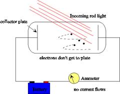
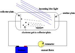
In 1902, Lenard studied how the
energy of the emitted photoelectrons varied with the intensity of the light. He
used a carbon arc light, and could increase the intensity a thousand-fold. The
ejected electrons hit another metal plate, the collector, which was connected
to the cathode by a wire with a sensitive ammeter, to measure the current
produced by the illumination. To measure the energy of the ejected electrons, Lenard charged the collector plate negatively, to repel the
electrons coming towards it. Thus, only electrons ejected with enough kinetic
energy to get up this potential hill would contribute to the current. Lenard discovered that there was a well defined minimum
voltage that stopped any electrons getting through, we'll call it Vstop. To his surprise, he found that Vstop did not depend at all on the
intensity of the light! Doubling the light intensity doubled the number
of electrons emitted, but did not affect the energies of the emitted
electrons. The more powerful oscillating field ejected more electrons, but the
maximum individual energy of the ejected electrons was the same as for the
weaker field.
 But Lenard did something else. With his very powerful arc lamp,
there was sufficient intensity to separate out the colors
and check the photoelectric effect using light of different colors.
He found that the maximum energy of the ejected electrons did depend on
the color --- the shorter wavelength, higher
frequency light caused electrons to be ejected with more energy. This was,
however, a fairly qualitative conclusion --- the energy measurements were not
very reproducible, because they were extremely sensitive to the condition of
the surface, in particular its state of partial oxidation. In the best vacua available at that time, significant oxidation of a
fresh surface took place in tens of minutes. (The details of the surface are
crucial because the fastest electrons emitted are those from right at the
surface, and their binding to the solid depends strongly on the nature of the
surface --- is it pure metal or a mixture of metal and oxygen atoms?)
But Lenard did something else. With his very powerful arc lamp,
there was sufficient intensity to separate out the colors
and check the photoelectric effect using light of different colors.
He found that the maximum energy of the ejected electrons did depend on
the color --- the shorter wavelength, higher
frequency light caused electrons to be ejected with more energy. This was,
however, a fairly qualitative conclusion --- the energy measurements were not
very reproducible, because they were extremely sensitive to the condition of
the surface, in particular its state of partial oxidation. In the best vacua available at that time, significant oxidation of a
fresh surface took place in tens of minutes. (The details of the surface are
crucial because the fastest electrons emitted are those from right at the
surface, and their binding to the solid depends strongly on the nature of the
surface --- is it pure metal or a mixture of metal and oxygen atoms?)
Question: In the above figure, the battery represents
the potential Lenard used to charge the collector
plate negatively, which would actually be a variable voltage source. Since the
electrons ejected by the blue light are getting to the collector plate,
evidently the potential supplied by the battery is less than Vstop for blue light. Show with an arrow
on the wire the direction of the electric current in the wire.
Einstein Suggests an Explanation
In 1905 Einstein gave a very simple interpretation of Lenard's results. He just assumed that the incoming
radiation should be thought of as quanta of frequency hf,
with f the frequency. In photoemission, one such quantum is absorbed by
one electron. If the electron is some distance into the material of the
cathode, some energy will be lost as it moves towards the surface. There will
always be some electrostatic cost as the electron leaves the surface,
this is usually called the work function, W. The most energetic
electrons emitted will be those very close to the surface, and they will leave
the cathode with kinetic energy
E = hf
- W.
On cranking up the negative voltage on the collector
plate until the current just stops, that is, to Vstop,
the highest kinetic energy electrons must have had energy eVstop
on leaving the cathode. Thus,
eVstop = hf - W
Thus Einstein's theory makes a very definite
quantitative prediction: if the frequency of the incident light is varied, and Vstop plotted as a function of frequency,
the slope of the line should be h/e.
It is also clear that there is a minimum light
frequency for a given metal, that for which the quantum of energy is equal to the
work function. Light below that frequency , no matter
how bright, will not cause photoemission.
Millikan's Attempts to
Disprove Einstein's Theory
If we accept Einstein's theory, then, this is a
completely different way to measure Planck's constant. The American
experimental physicist Robert Millikan, who did not
accept Einstein's theory, which he saw as an attack on the wave theory of
light, worked for ten years, until 1916, on the photoelectric effect. He even
devised techniques for scraping clean the metal surfaces inside the vacuum
tube. For all his efforts he found disappointing results: he confirmed
Einstein's theory, measuring Planck's constant to within 0.5% by this method.
One consolation was that he did get a Nobel prize for
this series of experiments.
► The
Compton Effect
As
learned ![]() on
the preceding pages,
on
the preceding pages, ![]() Einstein
proposed
Einstein
proposed ![]() the
hypothesis
the
hypothesis ![]() of
light quanta
of
light quanta ![]() and
succeeded
and
succeeded ![]() in
the explanation
in
the explanation ![]() of
the photoelectric effect.
of
the photoelectric effect. ![]() As
a result,
As
a result, ![]() it
has been established
it
has been established ![]() that
light exists
that
light exists ![]() in
the space
in
the space ![]() as
grains
as
grains ![]() (or
corpuscles or particles)
(or
corpuscles or particles) ![]() with
energy hf.
with
energy hf. ![]() The
particle nature
The
particle nature ![]() or
or
![]() corpuscular
nature
corpuscular
nature ![]() of
light
of
light ![]() was
more firmly
was
more firmly ![]() established
by
established
by ![]() the
discovery of
the
discovery of ![]() the
Compton effect.
the
Compton effect. ![]()
![]() In
1923,
In
1923, ![]() A.
H. Compton
A.
H. Compton ![]() (USA,
1892 - 1962)
(USA,
1892 - 1962) ![]() discovered
that
discovered
that ![]() the
scattering of
the
scattering of ![]() X
rays by a crystal
X
rays by a crystal ![]() can
be explained well
can
be explained well ![]() on
the basis
on
the basis ![]() of
the particle nature
of
the particle nature ![]() of
light.
of
light. ![]() (Of
course, the phenomenon
(Of
course, the phenomenon ![]() that
X rays are scattered
that
X rays are scattered ![]() by
crystals had been
by
crystals had been ![]() well-known
before.)
well-known
before.)
![]() The
scattering of X rays
The
scattering of X rays ![]() by
a particle
by
a particle ![]() (an
electron at present)
(an
electron at present) ![]() is
sometimes called
is
sometimes called ![]() Compton
scattering.
Compton
scattering. ![]() Compton
found that,
Compton
found that, ![]() if
we consider
if
we consider ![]() that
X rays collide
that
X rays collide ![]() with
the electrons
with
the electrons ![]() in
a crystal
in
a crystal ![]() as
if they were balls
as
if they were balls ![]() of
billiard,
of
billiard, ![]() Compton
scattering
Compton
scattering ![]() could
be explained well.
could
be explained well. ![]() To
formulate this process,
To
formulate this process, ![]() we
have to define
we
have to define ![]() the
momentum
the
momentum ![]() of
a light quantum.
of
a light quantum. ![]()
![]() Momentum
of a Light Quantum
Momentum
of a Light Quantum
It has been discussed ![]() that a
light quantum
that a
light quantum ![]() is a
"particle" with
is a
"particle" with ![]() energy
hf.
energy
hf. ![]() This
"particle" is considered
This
"particle" is considered ![]() to carry
a momentum
to carry
a momentum ![]() at the
same time,
at the
same time, ![]() because
we know that
because
we know that ![]() light
gives
light
gives ![]() a
pressure on the
a
pressure on the ![]() surrounding
wall.
surrounding
wall. ![]() How
large is the amount
How
large is the amount ![]() of the
momentum?
of the
momentum? ![]() Let us
study this below.
Let us
study this below.
![]() Consider
a container
Consider
a container ![]() filled
with light
filled
with light ![]() of
frequency f.
of
frequency f. ![]() Let the
pressure
Let the
pressure ![]() given
on the wall
given
on the wall ![]() of the
container
of the
container ![]() by the
light
by the
light ![]() be P
and
be P
and ![]() the
energy of the
the
energy of the ![]() light
per unit volume
light
per unit volume ![]() be U.
be U.
![]() We have
a relation
We have
a relation ![]()
![]()
![]()
![]()
![]() which
is proved
which
is proved ![]() by
experiment.
by
experiment. ![]() (This
relation
(This
relation ![]() can
also be derived
can
also be derived ![]() from
the classical theory.)
from
the classical theory.) ![]() From
this relation,
From
this relation, ![]() we see
that
we see
that ![]() the
momentum p
the
momentum p ![]() of a
light quantum
of a
light quantum ![]() is
given as p=hn/c=h/l
is
given as p=hn/c=h/l![]()
![]()
![]() Namely,
Namely,
![]() we can
say that
we can
say that ![]() the
momentum
the
momentum ![]() of a
light quantum
of a
light quantum ![]() is
given by
is
given by ![]() dividing
the energy
dividing
the energy ![]() by
by ![]() the
light speed.
the
light speed.
This result ![]() can be
obtained
can be
obtained ![]() by a
method similar to
by a
method similar to ![]() that through
that through
![]() which
we derived
which
we derived ![]() the
relation between
the
relation between ![]() the
molecular motion
the
molecular motion ![]() in a
gas and its pressure.
in a
gas and its pressure. ![]()
![]() The
Compton Effect
The
Compton Effect ![]() by the
Hypothesis of Light Quanta
by the
Hypothesis of Light Quanta
![]() Compton
found that,
Compton
found that, ![]() when
the monochromatic X rays
when
the monochromatic X rays ![]() are
illuminated
are
illuminated ![]() on a
graphite
on a
graphite ![]() (a kind
of carbon crystal),
(a kind
of carbon crystal), ![]() the wavelength
the wavelength
![]() of the
scattered X rays
of the
scattered X rays ![]() would
be longer
would
be longer ![]() as the
scattering angle
as the
scattering angle ![]() becomes
larger.
becomes
larger. ![]() This
cannot be explained
This
cannot be explained ![]() with
the classical theory.
with
the classical theory. ![]()
![]() In the
classical theory
In the
classical theory ![]() consisting
of
consisting
of ![]() Newtonian
mechanics
Newtonian
mechanics ![]() and Maxwellian electromagnetism,
and Maxwellian electromagnetism, ![]() the
incident X rays
the
incident X rays ![]() oscillate
the charged
oscillate
the charged ![]() particle
particle
![]() (electron
at present)
(electron
at present) ![]() and the
oscillating
and the
oscillating ![]() charged
particle
charged
particle ![]() radiates
around the same
radiates
around the same ![]() frequency
of electromagnetic
frequency
of electromagnetic ![]() waves
(X rays).
waves
(X rays). ![]() Accordingly,
Accordingly,
![]() the
frequency of the
the
frequency of the ![]() radiated
(scattered)
radiated
(scattered) ![]() X rays
X rays ![]() must be
the same as
must be
the same as ![]() that of
the incident X rays.
that of
the incident X rays. ![]()
![]()
![]()
![]() He
thought that
He
thought that ![]() the
incident X rays collide
the
incident X rays collide ![]() against
the electron
against
the electron ![]() in the
graphite
in the
graphite ![]() as a
"particle"
as a
"particle" ![]() with
the energy hn.
with
the energy hn. ![]() and the
momentum hn/c.
and the
momentum hn/c. ![]() Suppose
that the energy
Suppose
that the energy ![]() and the
momentum
and the
momentum ![]() of the
X rays
of the
X rays ![]() scattered
in the
scattered
in the ![]() scattering
angle
scattering
angle ![]()
![]() are
are ![]()
![]() and
and ![]() ,
, ![]() respectively.
respectively.
![]()
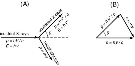
![]() The
electron
The
electron ![]() (the
mass = m )
(the
mass = m ) ![]() recoils
recoils
![]() with a
momentum mv.
with a
momentum mv. ![]() The
energies and momenta
The
energies and momenta ![]() in
Compton scattering
in
Compton scattering ![]() are
shown in
are
shown in ![]() the
following figure (A),
the
following figure (A), ![]() and the
relation
and the
relation ![]() of the
momentum conservation
of the
momentum conservation ![]() is in
the following
is in
the following ![]() figure
(B).
figure
(B).
![]()
The momentum conservation ![]() relation
is written
relation
is written
![]()
![]()
![]()
![]()
Since ![]() ,
, ![]() we have
we have
![]()
![]()
![]()
![]() Inserting
this
Inserting
this ![]() into
the above momentum
into
the above momentum ![]() conservation
relation,
conservation
relation, ![]() we get
we get
![]()
![]()
![]()
![]()
![]() On the
other hand,
On the
other hand, ![]() the
energy conservation
the
energy conservation ![]() is
written
is
written
![]()
![]()
![]()
![]()
![]() Therefore,
the difference
Therefore,
the difference ![]() between
the the wavelength
between
the the wavelength ![]() of the
incident
of the
incident ![]() and
scattered X rays becomes
and
scattered X rays becomes
![]()
![]()
![]()
![]()
![]() Accordingly,
the wavelength
Accordingly,
the wavelength ![]() of the
scattered
of the
scattered ![]() X rays
becomes
X rays
becomes ![]() longer
as the scattering angle
longer
as the scattering angle ![]()
![]() increases.
increases.
![]()
![]() Compton's
results
Compton's
results ![]() at the
scattering angles,
at the
scattering angles, ![]()
![]()
![]()
![]()
![]()
![]() and
and ![]()
![]() ,
, ![]()
![]() are
shown in the following
are
shown in the following ![]() figure.
figure. ![]() Each
graph represents
Each
graph represents ![]() the
intensity of X rays
the
intensity of X rays ![]() (ordinate)
(ordinate)
![]() as a
function
as a
function ![]() of
wavelength
of
wavelength ![]() (abscissa).
(abscissa).
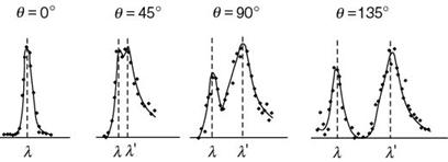
As the scattering angle ![]() increases
in the
increases
in the ![]() above figure,
above figure,
![]() the
intensity of X rays
the
intensity of X rays ![]() separates
into two peaks;
separates
into two peaks; ![]() the
right one of
the
right one of ![]() the
longer wavelength
the
longer wavelength ![]()
![]()
![]() shifts
to longer region.
shifts
to longer region. ![]() This
wavelength
This
wavelength ![]()
![]() is well
fit to
is well
fit to ![]() the
formula presented above.
the
formula presented above.
The wavelength ![]() of
another peak
of
another peak ![]() is just
the same as
is just
the same as ![]() that of
the incident
that of
the incident ![]() X-ray
beam.
X-ray
beam. ![]() This is
that scattered
This is
that scattered ![]() by the
whole atom whose
by the
whole atom whose ![]() mass is
quite large,
mass is
quite large, ![]() so that
the wavelength seems
so that
the wavelength seems ![]() not to
be varied.
not to
be varied. ![]()
![]() Thus
the particle
Thus
the particle ![]() nature
of X rays was
nature
of X rays was ![]() completely
confirmed.
completely
confirmed.
Incidentally, ![]() the
recoil electron
the
recoil electron ![]() could
not be detected
could
not be detected ![]() in
Compton's experiment,
in
Compton's experiment, ![]() but, a
little bit later,
but, a
little bit later, ![]() its
picture was taken
its
picture was taken ![]() with
with ![]() Wilson's cloud chamber.
Wilson's cloud chamber.
![]() Photon
Photon ![]()
![]() After
Einstein proposed
After
Einstein proposed ![]() the hypothesis
the hypothesis
![]() of
light quanta
of
light quanta ![]() in
1905,
in
1905, ![]() people
have been doubtful
people
have been doubtful ![]() of the
idea
of the
idea ![]() of the
particle nature
of the
particle nature ![]() of light
for
of light
for ![]() about
20 years.
about
20 years. ![]() However,
once they look
However,
once they look ![]() at the
experimental results
at the
experimental results ![]() of the
Compton effect,
of the
Compton effect, ![]() they
cannot help
they
cannot help ![]() convincing
themselves
convincing
themselves ![]() about
the theory
about
the theory ![]() of
light quanta.
of
light quanta. ![]() Then,
the particle of light
Then,
the particle of light ![]() (light
quantum)
(light
quantum) ![]() has been
called
has been
called ![]() photon,
photon, ![]() which
has been admitted
which
has been admitted ![]() into
the brotherhood
into
the brotherhood ![]() of
"particles"
of
"particles" ![]() like
electrons or protons.
like
electrons or protons. ![]()
Wave-particle
duality
This is the modern theory that
explains the nature of light, and in fact of all particles. It was described by
Albert
Einstein in the early 1900s, based on his work on the photoelectric effect, as
well as Planck's results. Einstein determined that the energy of a photon is
proportional to its frequency. More generally, the theory states that
everything has both a particle nature, and a wave nature, and various
experiments can be done to bring out one or the other. The particle nature is
more easily discerned if an object has a large mass, so it took until an
experiment by Louis
de Broglie in 1924 to realise that electrons also exhibited
wave-particle duality. Einstein received the Nobel Prize in 1921 for his work with
the wave-particle duality on photons, and de Broglie
followed in 1929 for his extension
to other particles.
l
= h/p
The propagation of light is governed by its wave
properties, whereas the exchange of energy between light and matter is governed
by its particle properties. This wave-particle duality is a general property of
nature. For example, the propagation of electrons (and other so-called
particles) is also governed by wave properties, whereas the exchange of energy
between the electrons and other particles is governed by particle properties.
The study of light and the
interaction of light and matter is termed optics. The observation and study of optical phenomena such as rainbows offers many clues as to the nature of light as well as much enjoyment.
The speed of light
See speed
of light. Although some people speak of the "velocity of light", the
word velocity should be reserved
for vector quantities (i.e.
those associated with a direction). The speed of light is a scalar quantity (i.e. it
has no direction), and therefore speed is the correct term.
Speed-of-light
formula
v =l f where l is the wavelength,
f is the frequency, v is the speed
of the light. If the light is travelling in a vacuum, then v = c,
thus c =l f
where c is the
speed of light. We can express v as v =c/n
where n is a
constant (the refractive
index) which is a property of the material through which the light is
passing.
Changes in the speed of light
All light
propagates at a finite speed. Even moving observers always measure the same
value of c, the speed
of light in vacuum, as c = 299,792,458 metres per second (186,282.397 miles per second);
however, when light passes through a transparent substance such as air, water
or glass, its speed is reduced, and it suffers refraction. Thus, n=1
in a vacuum and n>1 in matter.
History
of the measurement of the speed of light
The speed of light
has been measured many times, by many physicists. The best early measurement is
Olaus
Roemer's (a Danish physicist), in 1676. He had developed
a method for measuring light. He observed and noted the motions of Jupiter and one of its moonss with a telescope. It was possible
to time the revolution of the moon
because it was eclipsed by Jupiter at regular intervalss. Roemer discovered that the moon revolved
around Jupiter once every 42-1/2 hours when Earth was closest to
Jupiter. The problem was that when Earth and Jupiter were not as close, the
moon's revolution seemed to be more. It was clear that light took longer to
reach Earth when it was farther away from Jupiter. The speed of light was
calculated by analyzing the distance between the two planets at various times.
Roemer reached a speed of 227,000 kilometers per second (approximately
141,050 miles per second).
Albert
A. Michelson improved on Roemer's work in 1926. He used rotating
mirrors to measure the time it took light to
make a round trip from
Color and wavelengths
The different wavelengths are
interpreted by the human brain as colors, ranging from red at the longest
wavelengths (lowest frequencies) to violet at the shortest
wavelengths (highest frequencies). The intervening frequencies are seen as orange, yellow, green, blue, and,
conventionally, indigo. The frequencies
of the spectrum immediately outside the range the human eye is able to perceive
are called ultraviolet (UV) at the high
frequency end and infrared (IR) at the low.
Though humans cannot see IR, we do perceive it by receptors in the skin as heat. Cameras that can pick
up IR and convert it to visible light are called night-vision cameras. UV
radiation is not perceived by humans at all except in a very
delayed fashion, as overexposure of the skin to UV light causes sunburn, or skin
cancer. Some animals, such as bees, can see UV
radiation while others, such as pit viper snakes, can see IR using
pits in their heads.
Measurement of light
The following quantities and
units are used to measure light.
- brightness (or temperature)
- illuminance or illumination (SI unit: lux)
- luminous flux (SI unit: lumen)
- luminous intensity
(SI unit: candela)
GEOMETRICAL OPTICS
http://hyperphysics.phy-astr.gsu.edu/hbase/hph.html
Propagation of Light
Visible light is a narrow part of the electromagnetic spectrum and in a vacuum
all electromagnetic radiation travels at the speed of light:
![]()
The above number is
now accepted as a standard value and the value of
the meter is defined to be consistent with it. In a material medium the
effective speed of light is slower and is usually stated in terms of the index of refraction of the medium.
Light propagation is affected by the phenomena refraction, reflection, diffraction, and interference.
The behaviour of
light in optical systems will be characterized in terms of its vergence.
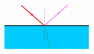
 Reflection
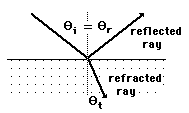
Light incident upon a surface will
in general be partially reflected and partially transmitted as a refracted ray.
The angle relationships for both reflection and refraction can be derived
from Fermat's principle. The fact that the
angle of incidence is equal to the angle of reflection is sometimes called the
"law of reflection".
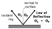
Law of Reflection
 A light ray
incident upon a reflective surface will be reflected at an angle equal to the
incident angle. Both angles are typically measured with respect to the normal
to the surface. This law of reflection can be derived from Fermat's principle.
A light ray
incident upon a reflective surface will be reflected at an angle equal to the
incident angle. Both angles are typically measured with respect to the normal
to the surface. This law of reflection can be derived from Fermat's principle.
The law of reflection gives the familiar reflected
image in a plane mirror where the image distance behind the mirror is the same
as the object distance in front of the mirror.
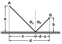
Fermat's Principle:Reflection
Fermat's Principle: Light follows the path of least
time. The law of reflection can be derived
from this principle as follows:
|
|
The pathlength from A to B
is
Since the speed is constant, the minimum time path is
simply the minimum distance path. This may be found by setting the derivative
of L with respect to x equal to zero.
|
Refraction
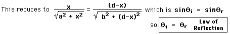
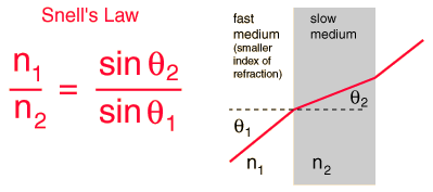
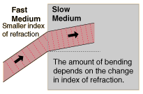
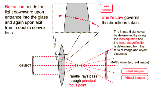
 Refraction is the
bending of a wave when it enters a medium where it's
speed is different. The refraction of light when it passes from a fast medium
to a slow medium bends the light ray toward the normal to the boundary between
the two media. The amount of bending depends on the indices of refraction of the two media
and is described quantitatively by Snell's Law.
Refraction is the
bending of a wave when it enters a medium where it's
speed is different. The refraction of light when it passes from a fast medium
to a slow medium bends the light ray toward the normal to the boundary between
the two media. The amount of bending depends on the indices of refraction of the two media
and is described quantitatively by Snell's Law.
Refraction is responsible for image formation by lenses and the eye.
As the speed of light is reduced in the
slower medium, the wavelength is shortened proportionately. The frequency is
unchanged; it is a characteristic of the source of the light and unaffected by
medium changes.
Fermat's Principle and
Refraction
Fermat's Principle: Light follows the path of least
time.
Snell's Law can be derived
from this by setting the derivative of the time =0.
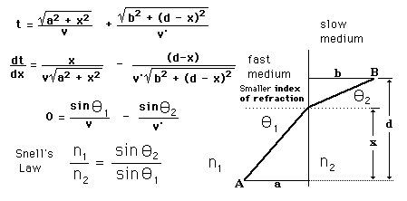
Snell's Law
Snell's Law relates the indices of refraction n of the two media
to the directions of propagation in terms of the angles to the normal. Snell's
law can be derived from Fermat's Principle or from the Fresnel Equations.

If the incident medium has the
larger index of refraction, then the angle with the normal is increased by
refraction. The larger index medium is commonly called the "internal"
medium, since air with n=1 is usually the surrounding or "external"
medium. You can calculate the condition for total internal reflection by setting the
refracted angle = 90° and calculating the incident angle. Since you can't
refract the light by more than 90°, all of it will reflect for angles of
incidence greater than the angle which gives refraction at 90°.
Total Internal
Reflection
When light is incident upon a medium of lesser index of refraction, the ray is bent
away from the normal, so the exit angle is greater than the incident angle.
Such reflection is commonly called "internal reflection". The exit
angle will then approach 90° for some critical incident angle qc , and for incident
angles greater than the critical angle there will be total internal reflection.
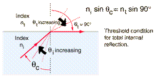
The
critical angle can be calculated from Snell's law by setting the
refraction angle equal to 90°. Total internal reflection is important in fiber optics and is employed in
polarizing prisms.
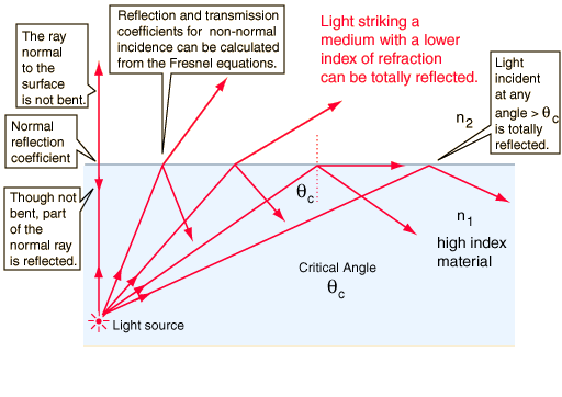
For any
angle of incidence less than the critical angle, part of the incident light
will be transmitted and part will be reflected. The normal incidence reflection coefficient can be calculated
from the indices of refraction. For non-normal incidence, the transmission and
reflection coefficients can be calculated from the Fresnel equations.
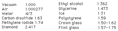
Index of Refraction
The index
of refraction is defined as the speed of light in vacuum divided
by the speed of light in the medium.
|
|
|
The indices
of refraction of some common substances are given below with a more complete
description of the indices for optical glasses given elsewhere.
The values given are approximate and do not account for the small variation of
index with light wavelength which is called dispersion.
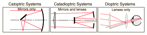
Mirrors in Imaging
Mirrors are used widely in optical instruments for
gathering light and forming images since they work over a wider wavelength range
and do not have the problems of dispersion which are associated with lenses and
other refracting elements.

Mirror Instruments
Mirrors are widely used in telescopes and telephoto
lenses. They have the advantage of operating over a wider range of wavelengths,
from infrared to ultraviolet and above. They avoid the chromatic aberration
arising from dispersion in lenses, but are subject to other aberrations.
Instruments which use only mirrors to form images are called catoptric systems, while those which use both lenses and
mirrors are called catadioptric systems (dioptric systems being those with lenses only).
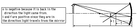
Mirror Geometry
Convex Mirror Image
A convex mirror forms
a virtual image.
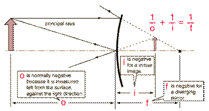
Using a ray parallel to the principal axis and one
incident upon the center of the mirror, the position
of the image can be constructed by back-projecting the rays which reflect from
the mirror. The virtual image that is formed will appear smaller and closer to
the mirror than the object.
Concave Mirror Image
If the object is outside the focal length, a concave
mirror will form a real, inverted image.
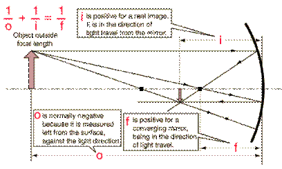
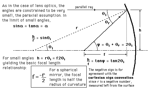
Spherical Mirror
Equation
The equation for image formation by rays near the optic
axis (paraxial rays) of a mirror has the same form as the thin lens equation:
![]()
From the geometry of the spherical mirror, note that
the focal length is half the radius of curvature:
![]()
As in the case of lenses, the cartesian sign convention is used here, and that is
the origin of the negative sign above. The radius r for a concave mirror is a
negative quantity (going left from the surface), and this gives a positive
focal length, implying convergence.
Lens in Imaging
Thin Lenses
In order to understand
lenses, one must first define some terms.
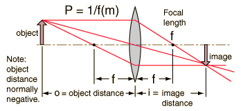
- The Focal
point is the location at which rays parallel to the optical axis
of an ideal mirror or lens converges to a point.
- The focal
length is the distance between the focal point and the middle of
the lens. It will be represented by F. You will also
see 2F being mentioned. 2F just
refers to two times the focal length.
- The distance
from the center of the lens to the object will
be referred to as do.
- The distance
from the center of the lens to the image will be
referred to as di.
- A Real
Image is an optical image at which rays from the object
converge. It is inverted
or flipped upside down.
- A Virtual
Image is a point from which Light rays appear to converge without
actually doing so. It is upright or in the same
direction as the object.
- A concave
lens is a lens thinner in center than
edges and is diverging.
- A convex
lens is a lens thicker in the center
than at the edges and is converging.
Principal Focal Length
For a thin double convex lens, all parallel rays will
be focused to a point referred to as the principal focal point. The distance
from the lens to that point is the principal focal length f of the lens. For a
double concave lens where the rays are diverged, the principal focal length is
the distance at which the back-projected rays would come together and it is
given a negative sign. The lens strength in diopters is defined as the inverse of the focal length in
meters. For a thick lens made from spherical surfaces, the focal distance will
differ for different rays, and this change is called spherical aberration. The focal length
for different wavelengths will also differ slightly, and this is called chromatic aberration.
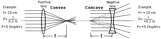
The principal focal length of a lens is determined by
the index of refraction of the glass, the radii of
curvature of the surfaces, and the medium in which the lens resides. It can be
calculated from the lens-maker's formula for thin lenses.
Focal Length and
Lens Strength
The most important characteristic of a lens is its principal focal length, or its inverse
which is called the lens strength or lens "power". Optometrists
usually prescribe corrective lenses in terms of the lens
power in diopters. The lens power is the inverse of
the focal length in meters: the physical unit for lens power is 1/meter which
is called diopter.
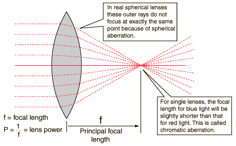
Image Formation
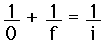
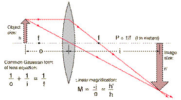
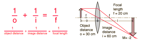
Thin Lens Equation
A common Gaussian form of the lens equation is shown
below. This is the form used in most introductory textbooks. A form using the Cartesian sign convention is often used in
more advanced texts because of advantages with multiple-lens systems and more
complex optical instruments. Either form can be used with positive or negative lenses and predicts
the formation of both real and virtual images. Does not apply
to thick lenses.

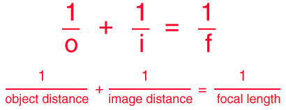
If the lens equation yields a negative image distance,
then the image is a virtual image on the same side of the lens as the object.
If it yields a negative focal length, then the lens is a diverging lens rather
than the converging lens in the illustration. The lens equation can be used to
calculate the image distance for either real or virtual images and for either
positive on negative lenses. The linear magnification relationship
allows you to predict the size of the image.
 Thin-Lens Equation:Cartesian
Convention
Thin-Lens Equation:Cartesian
Convention
The thin-lens equation in the Gaussian form is
where the Cartesian sign convention has been used. The
lens equation is also sometimes expressed in the Newtonian form. The derivation
of the Gaussian form proceeds from triangle geometry. For a thin lens, the lens
power P is the sum of the surface powers. For thicker lenses, Gullstrand's equation can be used to get the equivalent
power.
Cartesian Sign Convention
- All figures
are drawn with light traveling from left to
right.
- All distances
are measured from a reference surface, such as a wavefont
or a refracting surface. Distances to the left
of the surface are negative.
- The refractive
power of a surface that makes light rays more convergent is positive. The focal length of such a surface is positive.
- The distance
of a real object is negative.
- The distance
of a real image is positive.
- Heights above
the optic axis are positive.
- Angles
measured clockwise from the optic axis are negative.
Because the direction of light travel is consistent
and there is a consistent convention to determine the sign of all distances in
a calculation, this sign convention is used in many texts. It has some
advantages when dealing with multilens systems and
more complex optical instruments.
Magnification:Transverse &Angular
The linear magnification or transverse magnification
is the ratio of the image size to the object size. If the image and object are
in the same medium it is just the image distance divided by the object
distance.

The negative sign is used on the linear magnification
equation as a reminder that all real images are inverted. If the image is virtual, the image distance will be negative, and the
magnification will therefore be positive for the erect image.
If the media are different on the two sides of the
surface or lens, the magnification is not quite so straigtforward.
It can be variously expressed as

In this equation V is the vergence,
n is the index of refraction, and u is used for the angle.
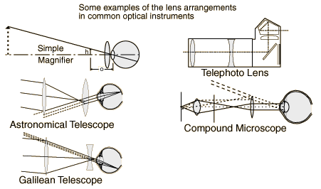
The angular magnification of an instrument is the ratio
of the angle subtended at the eye when using the instrument divided by the
angular size without the instrument. An important example is the simple
magnifier. The angular magnification of any optical system can be obtained from
the system matrix for the system.
Real Image Formation
If a luminous object is placed at a distance greater
than the focal length away from a convex lens, then it will form an inverted
real image on the opposite side of the lens. The image position may be found
from the lens equation or by using a ray
diagram.

If the lens equation yields a negative image distance,
then the image is a virtual image on the same side
of the lens as the object. If it yields a negative focal length, then the lens
is a diverging lens rather than the converging lens in the illustration. The
lens equation can be used to calculate the image distance for either real or
virtual images and for either positive on negative lenses. The linear
magnification relationship allows you to predict the size of the image.
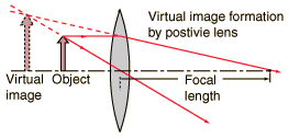
Virtual
Image Formation
|
A virtual image is formed at the position where the
paths of the principal rays cross when projected backward from their paths
beyond the lens. Although a virtual image does not form a visible projection
on a screen, it is no sense "imaginary", i.e., it has a definite
position and size and can be "seen" or imaged by the eye, camera,
or other optical instrument. |
|
|
|
A reduced virtual image if formed by a single negative lens regardless of
the object position. An enlarged virtual image can be formed by a positive lens by placing the
object inside the principal focal point. |
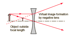
Diverging lenses form reduced, erect, virtual images.
Using the common form of the lens equation, f, P and i are negative quantities.


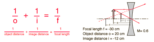
The lens equation can be used to calculate the image
distance for either real or virtual images and for either positive on negative
lenses. The linear magnification relationship allows you to predict the size of
the image.
Light Absorption
Light passing through an optical system can be
attenuated by absorption and by scattering. The exponential law of absorption
is the basic working relationship, but specific terms such as absorbance, absorptivity, and transmittance are widely used.
|
|
The differential
absorption can be expressed as
If the absorbing
medium is a solution, the concentration c is included and the law becomes
|

Optical Instruments
Prisms
A refracting prism is a convenient geometry to
illustrate dispersion and the use of the
angle of minimum deviation provides a good
way to measure the index of refraction of a material.
Reflecting prisms are used for erecting or otherwise changing the orientation
of an image and make use of total internal reflection instead of refraction.
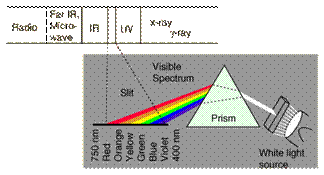
White light may be separated into its spectral colors by dispersion in a
prism.
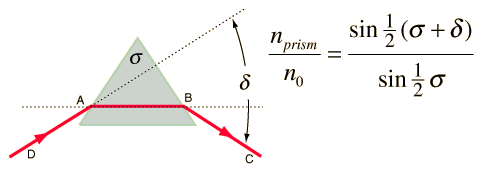
Prisms are typically characterized by their angle of
minimum deviation d. This minimum
deviation is achieved by adjusting the incident angle until the ray passes
through theprism parallel to the bottom of the prism.
An interesting application of refraction of light in a
prism occurs in atmospheric optics when tiny
hexagonal ice crystals are in the air. This refraction produces the 22° halo commonly observed
in northern latitudes. The fact that these ice crystals will preferentially
orient themselves horizontally when falling produces a brighter part of the 22°
halo horizontally to both sides of the sun; these bright spots are commonly
called "sundogs".
The angle of minimum deviation for a prism may be calculated
from the prism equation. Note from the illustration that this minimum deviation
occurs when the path of the light inside the prism is parallel to the base of
the prism. If the incident light beam is rotated in either direction, the
deviation of the light from its incident path caused by refraction in the prism
will be greater.
White light may be separated into its spectral colors by dispersion in a
prism.
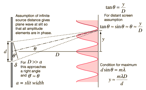
Double Slit Interference
Polarization by Reflection

Polarization by Scattering
|
|
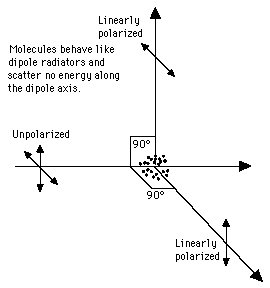
The scattering of light off
air molecules produces linearly polarized light in the
plane perpendicular to the incident light. The scatterers
can be visualized as tiny antennae which radiate perpendicular to their line
of oscillation. If the charges in a molecule are oscillating along the
y-axis, it will not radiate along the y-axis. Therefore, at 90° away from the
beam direction, the scattered light is linearly polarized. This causes the
light which undergoes Rayleigh scattering from the blue sky to be partially
polarized. |
OPTICS: powerpoint presentation